

A significant part of table design involves the legs and any framework connecting multiple legs to each other, to the table top, and to provide strength.
When it comes to the structure of the table, the joints between the legs and other parts of the table are where damage is most likely to occur. Pulling or pushing a table across the floor or kicking a leg exerts a force that attempts to separate the leg. Specifically, the force is levering apart the joint(s).
There are two types of levers that may be encountered.
Class 1 levers, where the force (the kick to the leg, or pushing or pulling it across the floor) is on the opposite side of the fulcrum from the load (the joinery or hardware trying to keep the leg connected). This is usually when the leg is driven into the table (e.g. kicked inwards).
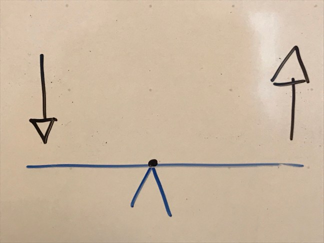
Class 2 levers apply when the force and load are on the same side of the fulcrum. This is most often seen when the bottom of the leg is driven away from the table (e.g. kicked outwards).

Let’s look at some examples of table construction and see how they compare.
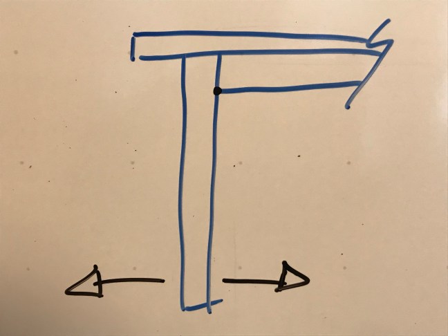
In this design, the end of the leg is attached into the bottom of the table top. The fulcrums are at the top edges of the leg and a force applied to the bottom of the leg has a lot of leverage and has a very good chance of overpowering the attachment method.

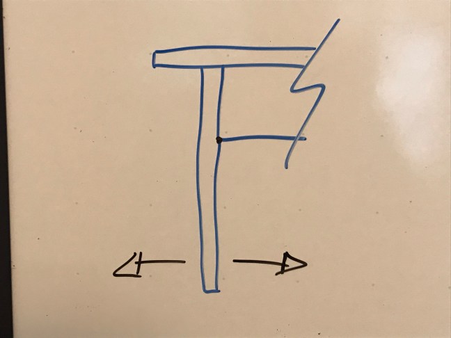
Adding an apron moves the fulcrum further down the leg, reducing the leverage of the force at the bottom of the leg. This design is considerably stronger than the previous.
Increasing the width of the apron lowers the fulcrum and further decreases the leverage on the joint, making the leg joint less likely to fail.
A diagonal brace has a similar effect as the wider apron. However, there is less joint area so the connection between the leg and other structural elements may be not as secure.

Adding a stretcher brings the fulcrum quite low and increases the strength of the leg connection. It would be difficult for a force applied to the bottom of the leg to break the joint.
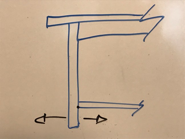
The lower the stretcher, the less leverage a kick has on a joint. If located at the very bottom of the leg (flush), the force of the kick has no leverage. This is not ideal for other reasons. As with most aspects of design, it’s all about making compromises.

For maximum strength, we would build all tables with wide aprons and low stretchers. However, sometimes we don’t want that look. We can use a weaker design if the abuse the table is expected to endure is not so much to break the table. We can also look at joint options as some are stronger than others.
The image below shows a top view of some examples of joints that could be used to join the table leg (on the left) to the apron (on the right).
In the discussion of strength of joint type, keep in mind that this refers to the resistance to prevent total joint failure – complete separation of the two parts. Many joints are prone to loosening over time, resulting in a partial failure. Sometimes retightening the joint is easy and other times it is not.
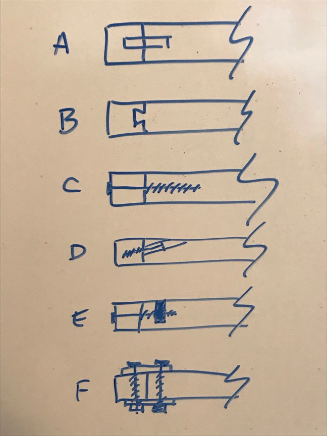
Example A illustrates a floating tenon joint. This joint has a lot of face grain gluing surface and that’s why it is strong. However, there is no mechanical interlock so the adhesive is doing all the work. Dowels are similar, but have less long-grain gluing surface so are inherently weaker.
Example B shows a sliding dovetail joint. You can see the mechanical interlock which makes this joint very strong, even without glue.
The last four examples use metal fasteners.
Example C is of wood screws through the leg into the end of the apron. Screw threads into endgrain don’t have very much holding power, so this is not a great option.
In Example D, the wood screws are reversed from the previous example and driven through angled holes (pocket holes) in the apron and into the side of the leg. These screws are biting into the long grain of the wood and therefore have much more strength. Another benefit of this joint is that the screws can be put in from the inside of the apron so they are hidden from plain sight.
Example E shows a variation of Example C. Rather than the screw being driven into the end grain, a dowel has been inserted from the back of the apron and the screw is biting into the long grain of the dowel, greatly increasing its pull-out strength. Stronger yet would be a bolt mating with a cross dowel inserted into the apron as drawn.
The last Example, F, shows two connecting plates attached to the table components with through bolts. This is a very strong connection. It’s also very conspicuous.
Discover more from Products From The Mind of Chris Wong
Subscribe to get the latest posts sent to your email.

Nice job on the article.
Nice job on the article.
Very helpful way to think through one’s design process. Thank you!
A – e looks like your trying to mount a breadboard end and not a way to mount a tableless on any substantial table. F looks like a mad women’s poop.
A skirt can only be so deep or you are not going to be able to get your legs under it if it is a dining table. There are traditional basic methods of mounting legs that work quite well if you can make a decent joint.
It is like making a chair without a stretcher: it will only last so long before it fails( the joints) .
The greatest problem is that there are too many out there without the skills and knowledge who are making things and or trying to teach.
Thank you for shariing this